I wrote that it was "a good thing that Jensen decided not to sponsor me". To be honest, I never really asked them for sponsorship, but did ask if I could get a reduced cost signal transformer from them. After no response from them for a couple of days I figured they decided I was a crank and were going to ignore me.
Instead, yesterday I got a very nice e-mail from Bill Whitlock, president of Jensen Transformers, telling me where my original transformer based designs were screwy, and that I should follow up with their sales group.
Sweet! And don't I feel like a jerk? Sorry Bill!
As an aside, Bill also decided to start ExactPower which I had written favorably before in the articles at PqLtd The two things that I like about their power envelope correction products are high efficiency and massive amounts of power line correction which can be done with it.
Now I'm kind of worried Jensen will send me a pair of their high quality transformers, which of course means that I'd be obligated to use them, and that will mean that I'll have to have a bigger circuit board made. Ah, the fear of success. :)
Thursday, June 29, 2006
Wednesday, June 28, 2006
Schematic V2.0
I decided that before going to production with my circuit board design to find a way to simulate the buffer circuit before hand. I found a shareware product called 5Spice which worked pretty well. I couldn't find a way to zoom in on the schematic, but beggars can't be choosers.
I truly long for the days when I worked for companies that could afford to purchase integrated schematic capture, simulation and PCB layout tools. It would have saved me the trouble of drawing the schematic twice, making my own NE5532 models, and then trying to use different keyboard shortcuts in each. Anyway....
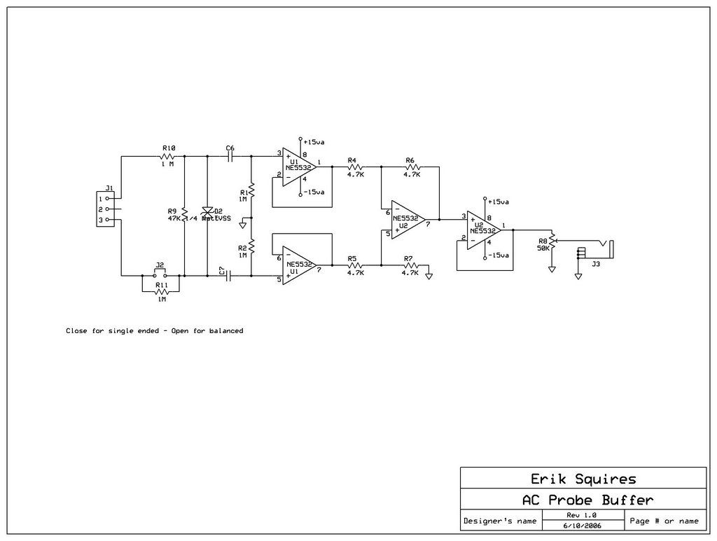
Based on the simulation analysis, I realised that because the voltage divider I was using was single ended, the power line signal shape I was seeing in Visual Analyzer were wrong. The neutral line noise was coming in at 1x while the line signal was 1/10x. Also, I didn't like the band pass characteristics I was seeing. Lastly, I realised that part of my problem was that the input impedance was so high that I was going to get much more noise than any real audio equipment would ever see.
So, with this in mind I redesigned the front end. Now, the input is balanced, the input impedance is reduced to around 55K, and the 115/240VAC switch will instead be used to allow me to short the AC line to ground, so I can see the neutral line noise separately. Don't worry, the input impedance will still be 50k, so no more than 3 mA will flow no matter what I do.
Which brings me to a small point about safety. Originally I did not want to shunt any current at all to ground. I was worried about noise on the ground line affecting my measurments as well as concern if the ground wire sould fail. Either in the case or between the case and the service connection. Also, for many reasons, I wanted the signal ground to float. In part it's because PC's have notoriously bad problems with ground loops. However, with the 50K resistors in place on both sides, the peak current that some one could face is 3mA. You'd can feel 1 mA, but 3mA apears to be safe. To put it in perspective, GFCI breakers installed in your kitchen trip at 10mA. 20mA is conisdered potentially lethal, and 16mA is considered the maximum amount of current that can flow through an adult and still be able to let go of the conductor. So based on all of this, I think it is in fact safe to connect the line and neutral to ground at this point.
Not shown in the schematic are 50mA 5x20mm fuses which will be on the hot and neutral side.
Also, I've changed the arrangement of the TVSS diodes. There are now two, and the'll fire at about 15-20 VAC (depending on which I decide to get, finally). This should ensure that even if a failure of the neutral or ground occur the buffer as well as any connected PC or audio equipment will remain safe. If I had more space, I would instead put in a "muting" cirguit like they use in op-amps and amplifiers so that if the voltage at either input of the buffer were too high it would disconnect, but I just don't have the space, and with 50K of input impedance I don't think anyone will be in danger. If my cat pees on it though, all bets are off, but that would be the case if he peed on my 300w/Ch InnerSound amp as well. So, UL be damned! :)
Sunday, June 25, 2006
Why IS my AC so bad?
 I've been wondering just why my AC was as bad as it is, so I've been doing some investigation. The THD measurement is around 7% right now. If you look to the right, there's a picture of part of the AC wafeform. The white circle shows a small negative spike. This is caused by the fluorescent lamp on my desktop. The bigger problem however was the severe drop at the top and bottom of each cycle. It's circled in read.
  After some experimentation, I discoverd that it is in fact being caused by a spike on the neutral coming from my laptop's power supply. The graph on the right is a graph of the neutral voltage at my desk. In an ideal world, it should be completely flat, and match the voltage at the ground pin but in my case every half cycle my laptop is putting a significant amount of current onto the neutral wire. Because the resistance between my desk and ground is not zero, the current flow causes a voltage spike to occur in the same direction as the incoming line voltage, with the effective result that the voltage between line and neutral dropping, and more noise and less effective power available to your equipment.
If I turn off the lamp and disconnect the laptop these neutral spikes disapear, the AC waveform becomes much cleaner looking and my THD measurements drop to under 3%.
All of this is great news, because it means I have at least two good ways to test the efficacy of any power conditioners that may come my way, especially those with special sockets for "digital" components.
Cheers!
Doh!
I realised as I was going to bed that if I wanted to drive 600 Ohm loads with the NE5532's I couldn't put a 50 kOhm pot in front of it.
So, today I'm experimenting with reversing the last op-amp and the pot. My biggest concern is that the power supply noise that was previously driven down by the 5:1 attenuation in the pot will come back up. If the noise looks low enough, I'll just make this one final change and have the board made. Otherwise I'm going to have to consdider adding more power supply filtering, and perhaps some RF filters on the input to the buffer and final stage.
Stay tuned!
Erik
Saturday, June 24, 2006
The Buffer Circuit
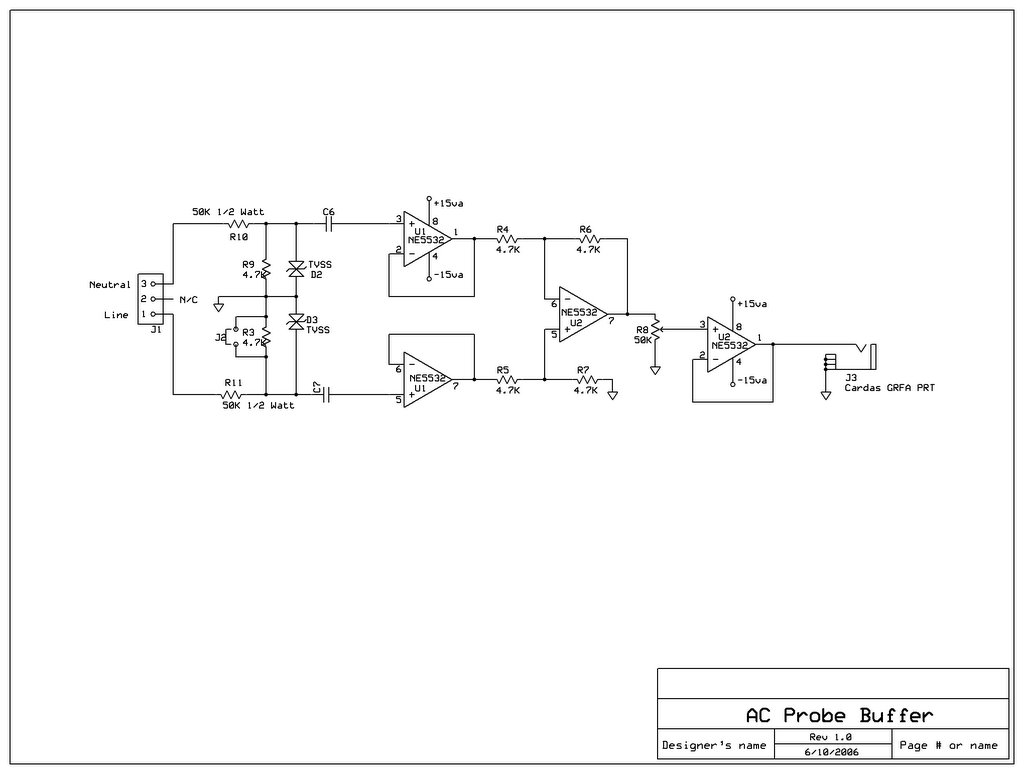
In the interests of full disclosure, I'm including the entire buffer circuit here for your perusal. The first section is a voltage divider which brings the 120 VAC down to a reasonable 5 VAC. There is a shunted 1 MOhm resistor there in case I ever want to compare an isolation transformer or balanced power regenerator a'la PS Audio. The jumper there will be connected to the 115/240 VAC selector switch on the back of the gutted power supply case.
There is also a place for a 15 VAC transient supressing diode made by Littelfuse in case I mess something up, I am hoping this will keep me from frying the laptop. After this, there are two 250VAC 0.1uF metal fil caps which couple the input stage to the amplifier buffer stage itself.
The buffer stage consists of NE5532 Op-Amps for several reasons. I have them, they are relatively low noise and low distortion, and they can directly drive a 600 Ohm load. In the circuit board design I was going to switch over to a single quad J-FET op-amp, the TL072, which are low noise but in the breadboard prototype I noticed some odd voltage drops when connecting the buffer to the mic input. This made me worry more about the mic input impedance than before.
Now, in an ideal situation, I would use a transformer of some sort to keep the current on the input side of the buffer from finding a way through ground to the neutral. However, good signal level transformers such as those made by Jensen Transformers are pricey, and I no longer have the room to put one in the board. Good thing they decided not to sponsor me, because I would have had to get a bigger circuit board. :)
The power supply is not shown, but it involves the salvaged bridge rectifier from the PC supply, 4x2,200 uF Panasonic FM caps feeding LM78L15 and LM79L15 voltage regulators, after which are a pair of 4.7uF tantalum caps, and perhaps a pair of 0.1uF metal film caps as well.
The last part of the buffer is a multi-turn pot. The mic input only accepts signals between +- 1 Volt. The buffer circuit is set to a gain of 1. So, becasue of this, the signal must be reduced from 5 Volts RMS on the output of the buffer to less than 1 Volt RMS on the Cardas RCA jack. When using a balanced input, I'll have to turn this back up a little.
The good news is that because there is so much attenuation, what little noise and ripple are in the op-amp outputs they get reduced by a factor of about 5, so I expect that my overall SNR will be quite high. I certainly can't see it in the scope measurements.
Before anyone goes nuts asking me why I didn't use this part or that, remember two things. First, I'm on a very tight budget. Second, I'm looking for relative differnces in performance of power conditioners. The normal THD+N measurement at my desk of the AC line is about 7%. Not 0.7%, but 7%! Probably two orders of magnitude greater than the buffer circuit I'm using. Also, I don't want to accidentally clean up the signal by putting too much in the circuit. The one exception I've made to this are fuses and a TVSS to keep me from frying anything. But the TVSS is off until it's overloaded.
So it Begins
The thing that got me started down this path, again, was finding a cheap way to make circuit boards. I found a place called Express PCB which has a prototyping service that costs $51 + shipping for small boards, along with free schematic and circuit board software. I started playing around with it, and then thought "What can I do with a circuit board that's really useful, and hasn't been done by everybody?" So that eliminated making my own headphone amp, preamp, amplifier, etc.
For a while after I thought of this blog, I was going to give up. I was adding up the parts cost, and it looked like I was going to have to spend $200 or just to get started. Too expensive for a hobby I thought(ok, you with the dual mono-block Jadis amplifier, stop snickering!) Then three things happened all together.
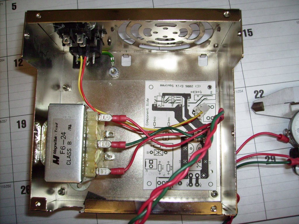
 First, I found that many of my needs would be served by this mini-PC power supply. I found it headed to the trash in the building I work at. It was a gold mine in disguise for the thrifty minded solder monkey that I am becoming. It included a grounded case, IEC electrical receptacle, DPST power switch, a 115/240 V switch which could be repurposed to become a balanced/unbalanced switch (more on this later), some existing fasterners for the circuit board, some jumpers and a bridge rectifier and even a plastic sheet on the bottom to lessen the chances of shorting something by accident. The paper you see in the bottom of the case is an ink-jet paper puppet of the future circuit board. By printing the top layer of the circuit board actual size, I can make sure that everything is in the right place before I get the board itself manufactured. You will also notice the heart of my power suppply, a 5 amp center tapped, 30 volt transformer, which will fit nicely in the corner.
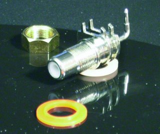 The second thing that happened is that this juicy bit-o-kit arrived in the mail, free of charge. Recognize it? It's a Cardas GRFA PRT printed circuit board (PCB) mountable female RCA plug. Usually around $20-$30 each. So, in a way, I had sponsorship. This doesn't mean that Cardas has in any way aproved of my blog, but now I feel obligated to use it, or pay for it. So, now a word about my sponsor. This is the sweetest RCA connector I've ever seen, or felt. The RCA plug sliding into it is absolutely butter smooth, but, the footprint is HUGE! I mean, it's great if you are making a high-end preamp, with a large circuit board and you are already putting in 0.1 uF capacitors the size of a cat's head, but in order to get the prototype discount I have to use a board that is exactly 3.8" x 2.5". This beast is literally the size of most the buffer circuit I am using. Fortunately most of it hangs off the circuit board, but still, it's huge. If you want to use these for production you will have to use tight tolerances between your boards and the case. The space between the ground pins and the start of the threads is only about .150 inches. If you are using round holes, your spacing drops rapidly. So, I can see why the case mounted versions are more popular with DIY'ers. The case mounted versions are just as good, and easier to manage. Leave these to the manufacturers paying the megabucks for the gold plated boards, and +-0.001" case manufacturing.
As an aside, the guys at HeadRoom managed to stick 3 double sockets plus a single in the back of Desktop Headphone Amplifier along with a DAC, amplifier and power supply in their design. That's pretty impressive if you ask me.
The third thing is that I found really cheap PC Oscilloscope software that seemed to work pretty well. I found two good sources, but ended up going with Visual Analyzer because it's frequency counter was more accurate, and it had a built in function generator.
In my next post, the buffer itself. For those of you who want to see exactly what I mean by "easily flammable!"
For a while after I thought of this blog, I was going to give up. I was adding up the parts cost, and it looked like I was going to have to spend $200 or just to get started. Too expensive for a hobby I thought(ok, you with the dual mono-block Jadis amplifier, stop snickering!) Then three things happened all together.
 First, I found that many of my needs would be served by this mini-PC power supply. I found it headed to the trash in the building I work at. It was a gold mine in disguise for the thrifty minded solder monkey that I am becoming. It included a grounded case, IEC electrical receptacle, DPST power switch, a 115/240 V switch which could be repurposed to become a balanced/unbalanced switch (more on this later), some existing fasterners for the circuit board, some jumpers and a bridge rectifier and even a plastic sheet on the bottom to lessen the chances of shorting something by accident. The paper you see in the bottom of the case is an ink-jet paper puppet of the future circuit board. By printing the top layer of the circuit board actual size, I can make sure that everything is in the right place before I get the board itself manufactured. You will also notice the heart of my power suppply, a 5 amp center tapped, 30 volt transformer, which will fit nicely in the corner.
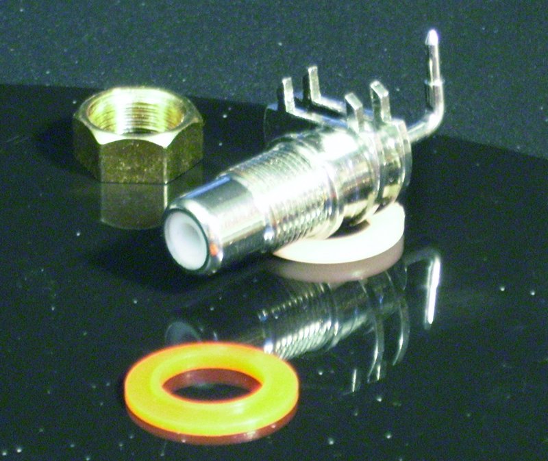 The second thing that happened is that this juicy bit-o-kit arrived in the mail, free of charge. Recognize it? It's a Cardas GRFA PRT printed circuit board (PCB) mountable female RCA plug. Usually around $20-$30 each. So, in a way, I had sponsorship. This doesn't mean that Cardas has in any way aproved of my blog, but now I feel obligated to use it, or pay for it. So, now a word about my sponsor. This is the sweetest RCA connector I've ever seen, or felt. The RCA plug sliding into it is absolutely butter smooth, but, the footprint is HUGE! I mean, it's great if you are making a high-end preamp, with a large circuit board and you are already putting in 0.1 uF capacitors the size of a cat's head, but in order to get the prototype discount I have to use a board that is exactly 3.8" x 2.5". This beast is literally the size of most the buffer circuit I am using. Fortunately most of it hangs off the circuit board, but still, it's huge. If you want to use these for production you will have to use tight tolerances between your boards and the case. The space between the ground pins and the start of the threads is only about .150 inches. If you are using round holes, your spacing drops rapidly. So, I can see why the case mounted versions are more popular with DIY'ers. The case mounted versions are just as good, and easier to manage. Leave these to the manufacturers paying the megabucks for the gold plated boards, and +-0.001" case manufacturing.
As an aside, the guys at HeadRoom managed to stick 3 double sockets plus a single in the back of Desktop Headphone Amplifier along with a DAC, amplifier and power supply in their design. That's pretty impressive if you ask me.
The third thing is that I found really cheap PC Oscilloscope software that seemed to work pretty well. I found two good sources, but ended up going with Visual Analyzer because it's frequency counter was more accurate, and it had a built in function generator.
In my next post, the buffer itself. For those of you who want to see exactly what I mean by "easily flammable!"
What is this Anyway?

Welcome!
This blog is all about the quality of AC power that reaches our homes, and what audiophiles and videophiles can do about it.
For a complete discussion on power conditioners, go to an article I wrote years ago, here: PQLTD.COM Power Conditioning. You may have seen articles which have a similar structure or wording. As far as I know, my article came first.
What makes this blog special? First, what I'm doing is dangerous. Unlike your average reviewer of power conditioners, who sits in a posh air conditioned room, surrounded by thousands of dollars of audio equipment he didn't pay for, sipping wine and listening to his boundless collection of CD's, I will risk life and limb in each posting. I'm actually going to be connecting the AC power to my laptop through a specially designed buffer. I'm going from the AC power to my laptop with no more than a couple of resistors, film caps and an op-amp in between. Oh, did I mention I don't actually know that much about what I'm doing? That's right, it's all an experiment. Just think of a hill-billy strapping a rocket to the top of his Ford F-150 and you'll get the idea.
Second, I am not going to listen to the conditioners. In a world where stones and cable lifters are being used to tune systems to the "heights of realism" in high end audio systems, I think it would be too easy for me to ascribe a quality to the sound of a power conditioner which it doesn't have. The other problem is that honestly, the better your equipment's power supplies, the less effect a power conditioner will have.
More in my next post!
Cheers,
Erik
Subscribe to:
Posts (Atom)