Wednesday, August 16, 2006

The Conrad Johnson PV-Erik

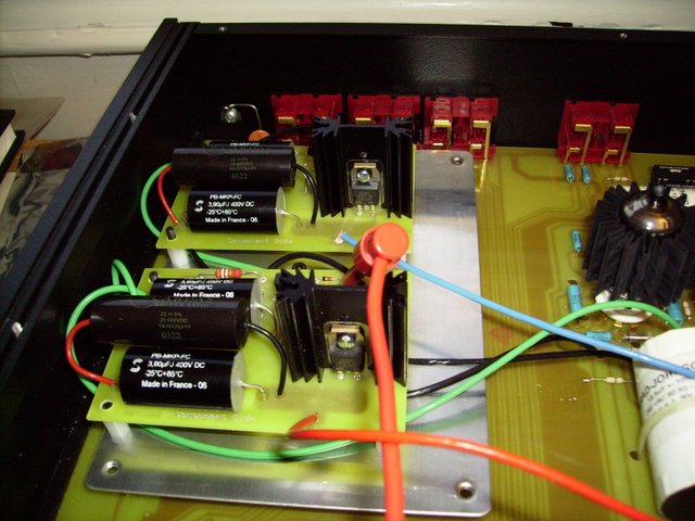
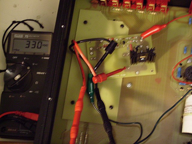
Here is another picture, this time from behind, and with all of the wires in place.

There are several major changes. In the front (top of the pic), where the Necromonger heat sink is, the original power supply was upgraded to produce 360V, at 1A if needed.

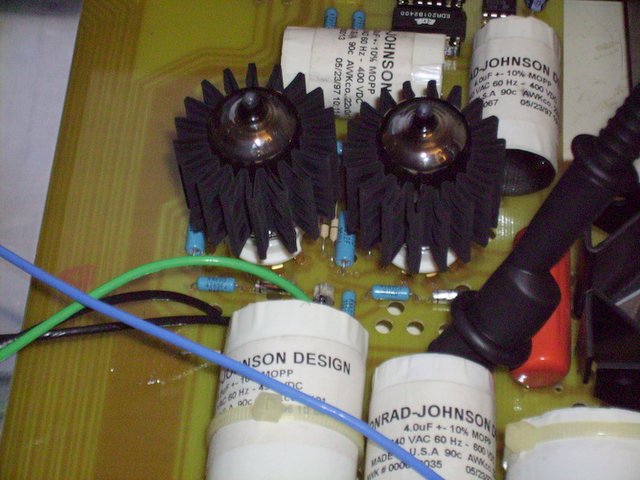
To the right are the dual mono supplies that take the 360 V and feed each tube 330 independently. Towards the back you can see the red and blue wires (red for Right, of course!) which feed each tube independently, as well as a better picture of the Azuma sockets. I was able to take advantage of unused component holes for these, all I did was enlarge them slightly so I would be able to use enough of the wire to get a solid connection.

The wiring is all Cardas 14 ga. Litz copper wiring. Most of the solder was Cardas, but I admit that some of it, especially for the diodes and resistors, was just Radio Shack silver content solder. I just couldn't wait for the shipment from the Parts Connection to arrive. All resistors are metal film, but not particularly high quality. I did get some Dale/Vishay resistors from Mouser, which were only $0.30 each for the 18k coupling resistor.

The two black wires carry the 360 V from the original regulator stage to the two new stages. There is only one ground wire. This was mostly caused by the fact that I had a really hard time soldering 14 ga. wires with a 40 watt soldering gun. I eventually got the knack of it, but for now, this is how it will have to be. The PCB was designed for this from the start, and will help keep the star grounding method of the original board. Posted by Picasa

Thursday, August 10, 2006

Recognize Me?

Tell me honestly, it's not that easy to tell that you are looking at the insides of a PV-10 now is it? Some day some one is going to make a living restoring these things, and they are going to open this up and go "what the f****??!!"  Posted by Picasa

Tubes in a Shroud

While I was ordering parts from the Parts Connexion I also went ahead and got some upgrades for the tubes. What you are looking at are the 12AU7's in Perl tube coolers. In case you are wondering, yes, they really do remove a lot of heat from the tube itself. Whether that will have any benefit at all in the long run, I have no direct experience.

If you look carefully you'll also see the white of the new sockets peeking out. These are Azuma ceramic sockets with gold plated pins. As far as I know, these were the best sockets I could find which could be made to fit. They come with a gold plated pin in the center. Fortunately a little time with a hand drill and they pop right off, leaving the rest of the socket in perfect condition.
Some Tube-o-philes prefer the brown resin sockets which were original with the preamp. They think it's microphonics are the best, and the contacts are good enough. I looked at the contacts, they looked nasty. I'm sorry, they were going. If I every decide to worry about microphonics, that's what the tube coolers will do. Posted by Picasa

Droolicious caps!

The boards are now fully assembled, and I managed to figure out a way to mount them that didn't violate the fundamental laws of physics. Take a look! Each board has a pair of 3.9 uF Solens and a single Cardas 0.22uF bypass cap. Also, all the wiring and most of the solder is Cardas as well.  Posted by Picasa

Conrad Johnson Power Supply Evolution

There's an interesting article over at Stereophile which is mostly about the CT5 preamplifier, but it also talks about how they have moved away from multiple regulation stages as they did in the PV-12 and other preamps, to simplify the design.

I still need the first stage to help drop the voltage, becuase I'm still toying with the idea of removing or reducing the resistor between the two storage caps. Also, by doing it this way, I'm adding more storage capacitance than I would otherwise. I've added nearly 16uF to the overall design, 8uF per channel. That's pretty good at 330V!

Tuesday, August 8, 2006

Voltage Regulator Schematics


The voltage regulator stages should be familiar to anyone who has worked with Conrad Johnson PV series preamps in the past. The main differences are the output transistor as well as the selection of zener diodes. There is also a difference in the resistor beneath the first diodes, but this value does not seem to be very important. CJ specs 0.15 PS caps for bypass caps which I have been told were made by MultiCap. Frankly, I'm not only running out of room but I wanted to try the Cardas caps in this project, so I'll be using a single 0.22uF Golden Ratio bypass cap across the output filter cap. If I can find enough space for them.

Saturday, August 5, 2006

Assembling The Mounting Plate

It's still very much a work in progress, but I figured out how to mount the power supplies without gutting the phono stage layout beneath. I'm going to use a mounting plate to mount the boards on. Take a look below. Tell me, honestly, are you CJ fans out there shocked at the metamorphosis happening? :) More when I actually figure out which order the screws have to go in.  Posted by Picasa

Friday, August 4, 2006

Pinup shot

In case you are wondering what the boards look like when there are parts in them, here you go. The big Solen and Cardas caps are still missing, which is why the board looks so naked. When they go in you'll see that all the spare real estate disapears.  Posted by Picasa

It's alive!

Ok, this is just incredibly exciting! :) I assembled all of one board except for the storage caps which are still en-route, used some component leads I had lying around (suddenly I have LOTS of them) for temporary test points, and hooked it up with jumpers to the PV-10s power supply.

Check out the reading on the Fluke next to it, 330 Volts!!! Perfect! Not bad considering I layed out the PCB from scratch, huh?

I'm going to try to finish assembling the other board tonight, and if I have time test it. I probably have another week before the storage caps arrive in the mail, so between now and then I have to figure out a way to mount these boards so that they don't short something and without ruining the underlying phonograph stage layout.

Do you see that large fiberglass "plate" held on by four black screws? Underneath that are all the holes and traces for the phonograph stage. If you had paid another $200 those holes would be filled with the actual parts. For some strange reason, the underlying B+ is still hot. I say strange because Conrad Johnson had to add a jumper in order to make it hot, when they could have just omitted the jumper, and avoided the trouble of putting this cosmetic cover on altogether. Well, who knows what they were thinking. But you'll see how this will work to my advantage in future postings. Stay tuned! Posted by Picasa

Wednesday, August 2, 2006

Honest honey, it's just a few parts...


The first shipment has arrived! Almost all of the non-premium parts have arrived. This means all the diodes, all of the resistors, all the transistors, heat sinks and some mounting hardware and a little metalized film bypass cap. Sorry folks, this is a Panasonic E seriss. I simply could not find a small enough 0.010 cap from any of the premium vendors. They were all too large physically, and way over rated voltage wise. The baby Panasonics are just going to have to be good enough. I will make up for them by adding Cardas in the output caps. Honest!

Even though the main storage caps for this stage won't get here till next week, I can assemble the boards and try them out, to make sure they work, and begin the work of altering the circuit that is on the original.

I'll post more when the soldering iron is hot and I'm ready to start stuffing. Posted by Picasa

Tuesday, August 1, 2006

Building a PV-Erik, or PV-Frankenstein, depending on how you see it.


So, I last wrote that I was fixing a Conrad Johnson PV-10, which was true, but I also wrote that I would be returning to power conditioning, which is only partially true.

Instead of focusing on the power conditioner testing which I had planned, I instead started looking around at the CJ schematics for the PV-10 and 12, and with some helpful ideas from UncleStu at Audio Asulym I decided I would transform my PV-10 into a PV-10 on mega steroids. The challenge is to make it as good of a preamp of it's kind as I could, without actually harming the reasons I fell in love with it in the first place, and I think I have a way of doing this. By leaving the audio circuit 99% untouched, and focusing the work I do on the power supply.

If you scroll down you'll see the insides of a PV-10AL. Notice all that bare space to the right? That's where the phonograph section would normally go if you bought the PV-10A (sans 'L'). In this space I am going to stick two of these circuit boards which you see pictured. They are power supply boards, one for each tube. This will hopefully improve channel separation, power supply regulation, and bass response. They will be chock full of Solen and Cardas Golden Ratio capacitors.

By the way, this is the first PCB I've ever designed for myself. I've designed many, but always for a client or employer. This is the first time I've done one and paid for it out of my own pocket. Pretty nice huh? The design is based on the B+ power supply regulator stages used in the PV-5 through PV-12. It's a little different in that I'm using a TIP50 transistor, which gives me higher breakdown voltages and seriously higher power dissipation than the MJE340s which CJ is so fond of, and seem to blow out so regularly in the preamps this old. So, serious overkill here.

The first batch of parts arrive from DigiKey tomorrow, and then about a week later the fancy caps, jumper wire, etc. arrive from The Parts Connexion.

Stay tuned folks, this really is going to be a major overhaul of the power supply of this preamp, and I'll be documenting all the way.

I think you will see that the mods all stay true to the original circuit philosophy. The only mods I intend to the audio circuit itself are a pair of 0.22uF Cardas caps. Maybe. If I like it. Let's see what the power supply mods do to this baby giant killer first. Posted by Picasa