Saturday, October 28, 2006

The Long Way Home


Gentle Reader (and I do mean singular!),

I'm happy to say that the power supply rebuild has all but finished. Let me walk you through the pictures. First, is a picture of the original, unadulterated board.

Notice the large cap in the middle next to the transformer? If it was a can of beans you would have had to throw it out for having expanded beyond it's size. My work was cut out for me.

Replace every electrolytic capacitor and every cement resistor. First job was to remove every single part. Leaving me with a very naked board, like this one.

I removed the two main transistors and their heat sinks so I could take better measurements of the circuit board and the holes underneath.

After removing all the parts, I like to add parts back based on the height of the parts. The smallest parts, or those which are closest to the board go in first, then I move my way vertically. This basically meant that the 22uF capacitors went in first, then the power resistors, and then the big filter caps next to the tranformer.

I know it makes me seem old-school to say this, but I really am amazed at how much smaller and better components are today than they were just 10 years ago. Let me show you the finished board to explain.


Look at just how small the caps are compared to the originals. Also, see those tiny black resistors? Believe it or not, they are 5 Watt Mills non-inductive wirewound. You can't get any quieter than this friends, and they are tiny compared to the cement resistors they replace.

You might notice the canary yellow trim-pots which have suddenly apeared too. These are definitely a nice upgrade. The originals were open, carbon composites. These are sealed conductive plastic trim pots. Smooth as honey, electrically quiet, and have much better long term reliability and stability than the originals. Unfortunately one thing I did find when I put everything back together is that the 5V outputs were far too low, which I think is due to a bad transistor. Not a huge deal, but it means the tuner won't be put back together this weekend.

Friday, October 27, 2006

Mid-Terms are Over, Mostly..

Which means, I can take a little break from the world of academics and focus on the power supply. Mikel at the FM Tuner Group suggested I should upgrade one cap to an 80V or better unit, which is on order, but everything else I think I need I have, so Saturday I begin the overaul, and perhaps begin the mechanical drawings on a PS upgrade.

You know, many people whose opinion I respect say that the power supply in the 3001/A is very good, and I mostly agree, but it's not what I would call spectacular. In particular, you have a situation where all of the filter and storage capacitors are on high impedance paths away from the voltage regulation stages. The voltage regulators are kind of live and let live when it comes to all of the different boards they supply. Each board contributes a portion of the overall filtering, but electrically each board is far from the regulators, so sags in the main regulators may take unnecessarily long periods of time to correct. It's all very touchy-feely. Each board can affect all the other boards to some extent.

So, my research is going to be in creating a daughter board to allow the regulator transistors to dominate the output voltages, letting the filtering on the individual boards relax and no longer worry about what the other boards are doing to the supply, and shorten the effective distance between the regulators and the boards themselves. Maybe. I only sold a few of the output boards, so if I do this next step it will be a one off. The good news is that from my initial research I can do it all in a non-destructive manner. I think. Well.....

Thursday, October 19, 2006

Digital Camera Cases

Since my GF has adopted my old digital camera, I bought a new one, and then I went out shopping for a camera cover for it.

I have come to the conclusion that there really is no such thing as a good one.

I bought a Tamrac Neo, which I guess means it's made of neoprene, that stretchy fabric they use in wet suites. I have to tell you all, that it's not designed to protect the camera from anything but dust, scratches and mild finger taps. There is no real cushioning in the case at all. It's just stretchy fabric. I also bought a little case for my Pentax Optio. It fell off the strap of my back pack as I was walking to the train, and it has never been the same since. There was almost no padding in that one either.

So, seriously, Tamrac, what are you, and all your competitors thinking? I can't beleive that it's all that difficult to put some foam, something, anything mroe in these cases. Even shock absorbing jell.

On top of all this, the neo case is actually made much bigger than it needs to be by the ultra wide back which the neoprene is sewn onto. I can but hope that some industrious Chinese textile mill will read this and start producing genuinely protective portable case for digitals.

Thursday, October 12, 2006

Connector Porn

First, a little tease with the shrouds fitted over the jacks, enlarged slightly to fit the threads. The cross resistor is a fix to a problem in the Rev 1.0 boards, which is fixed in 2.0.


Second, a coy shot from the side with the shrouds removed for your viewing fancy.

Naked Cardas jacks, Vishay Dale Resistors and all the other parts an audiophile needs to listen to ensure his listening satisfaction.

Isn't that a lovely thing? Beautiful high performance jacks reflected in a pool of plated copper. Makes the electrons weep to be still.


Lastly, a sadly out of focus picture from behind, the burn marks proof of a poorly trained and inexperienced solder monkey trying to fix a mis- aligned jack.

You really must be sure you put the jacks in straight, because desoldering them after is insanely difficult. I almost gave up and took the board apart.

Real Pics!

Finally, I have pics to show you, my faithful reader (singular, hah!) Take a look at what it looks like installed in the back of my 3001. The missing screws below the switch is because I lost it. The board fit perfectly. More pics shortly. Posted by Picasa

Tuesday, October 10, 2006

It's Your Turn Now

I realise that in part my postings are kind of rambling in lieu of people talking back to me. I haven't gotten a single comment here about the upgrade boards. I have 6 people on e-bay watching to see if the boards will sell, one e-mail asking for 2.0 boards, but no one else really talking to me about what they would like to see, or whether they like the idea or not.

So, if you are reading this blog with interest, please, drop me a comment, tell me what you like, what you are thinking, what you are working on. Are you wanting the 2.0 boards, but want to see if other's will commit first? Do you wonder if modding this venerable tuner is worth the effort now, or are you busy with school and work so you want to upgrade, but not now? What's goin gon?

Thanks!

Reviews are coming? Maybe.

I got a little good news yesterday, a Tandberg owner has asked me to sell two output boards to him to be installed by a well known FM tuner guy. I'm hoping that I can get some feedback from him which I can use to improve any mistakes I haven't caught, as well as encourage other's to purchase the remaining 2 boards or give me reason to make the 2.0 run.

I've also been doodling a PS daughter-card design. I am pretty sure I'll be able to do the PS mod board. It will be either a tweaker's delight, or a perfectionists heaven, adding a great deal of bottom end to the sound, and maybe reduce overal tuner noise, as well as making the PS incredibly reliable, especially with the early models.

Sunday, October 8, 2006

Tandberg PS - Fantasy Land

Ok, I take it back. There are some major upgrades I would do to the power supply if money were no object:

  • Double the output transistors used for the 25V and the 15V outputs. This means Q805 and Q811. I haven't done all the math yet, but I think I should be able to keep the original design, without having to entirely redesign the section before.
  • Add around 600uF of storage right before these transistors.
  • Possibly add around 250uF of storage after them.

The benefits would be:
  • Cut the power dissipation in half for each transistor,
  • Adding significant heat sink radiating area,
  • Decreasing the output impedance of the power supply
  • Huge increase in the dynamic current output of this stage.
Having the 1000uF storage cap 1R2 away from the output transistors is just sad. And having no capacitance on the output is also kind of sad. Admitedly, the boards that this goes to all have their own filtering, but at least some polyester film caps on the outputs, if not some more serious filtering would not kill anyone. I'm really kind of impressed that this tuner achieved what it did with such limited power supply capacitance, but this explains a lot of the inductors being used as power supply filters as well.

"But isn't this overkill?" the weak would ask, and we'd say "hell yes!"

Perhaps there is a way to do this with the original, without throwing out the original, either by modding the existing board, or perhaps creating a small upgrade board like I did with the PV-Erik, allowing you to retrofit it. Hmmmmm, I'll think about this as I'm removing caps.

Doh, yes, of course you can buy them assembled!

Sorry for being so dense. I have spent so much time reading around at the FM Tuner Info Site I really thought most people with these tuners would be hobbyists like me, with too many parts and solder lying around, but I realised that many of the people who enjoy listening to the sexiest tuners in the world (Tandbergs of course!) may not be the solder monkey that I am. So, yes, you can buy the fully assembled boards. I will still need the original for the de-emphasis switch, but all the other parts are orderable. So, if you want to upgrade your tuner outputs but are afraid of doing anything more complicated than removing some panel screws and pulling an IC out of it's socket, no problem.

Prices still to be determined, but not cheap, the Cardas jacks are $10 a piece, plus the board, plus the connectors, and of course labor which is distracting me from school and a girlfriend who want to know how it is I say I am broke, but can somehow afford to purchase the last two boxes of hand made NOS carbon film resistors found in an abandonded Shinto Shrine in a mountain of Yokohama which are still so slightly radioactive that they must be smuggled into the country hidden in 100lb cases of marijuana to avoid alerting Homeland Security.

Am I the only one with these problems??

I'll pull out your heart you filthy bastard!

This is what I get for watching Venture Brothers before typing. :)

Ok, it's not a bastard, and it's not it's heart but the power supply. For the next stage of the rebuild I've pulled the power supply completely out of the case. This will let me get to all the parts, and test it without risking the rest of the unit.

I plan the following upgrades:
  • Replace all cement resistors with Mills Wire-wound low inductance 5 watts. This is a significant wattage upgrade as well.
  • Replace every electrolytic cap. If the voltage required is 50 or less, use Panasonic FM, otherwise FC. Bypass critical caps under the board.
  • Replace carbon open frame trim pots with either ceramic or conductive plastic closed frame both of which are quieter and more stable. The conductive plastic pots are better, but lower wattage. I'll have to investigate why one of the originals got cooked before I can commit to them.
This is also a board which could benefit from an upgrade, but I don't think there's enough interest out there. It would be significantly more expensive than the output boads which I don't think I'll sell enough of the prototypes, let alone any production runs. But, if I can use this blog to fantasize a little, I would:

  • Size the footprints for Panasonic FM caps, Mills 12 Watt power resistors
  • Use double sided, 2.5 oz. silver plated boards
  • Improve the tuner's cooling by:
    • Using much better, taller heat sinks closer in design to what I used in the PV-Erik. The downside of these is that their footprint is huge by comparison, which is another reason why the double sided baord and smaller parts elswhere will be important.
    • Add more vent holes directly under the heat sink fins
    • Add TO-220 heat sinks to a few of the smaller transistors. This will make warm up a little longer, but greatly improve reliability. They will probably never fail due to heat stress again.
  • For each 1,000uF cap I would use two 500uF-600uF caps to get lower inductance while keeping the same or slightly higher storage
  • Add metal film bypass caps on all the critical electrolytics.
  • Use the best modern ultra-fast recovery diodes for the bridge rectifiers.
  • Improve the traces by:
    • More than doubling the copper weight
    • Thicker, better traces.
    • Huge power and ground planes
If I could get enough orders, I would probably be serious about it, but the bare board would probably run around $400, so for now, I will just start replacing parts as I take a break from school. Maybe by Christmas I'll actually be listening to NPR. Or sending the 3001 to a tuner expert who can get the RF portions tuned up. Or I'll start replacing all the other electrolytics in the system. More likely I'll be trying to catch up because I was soldering instead of studying. :)

I'll post more if I get another digital camera, or after I have done the PS uprgrade.

Take care!

Saturday, October 7, 2006

It all fits, and looks great!

It is a real real shame that my Pentax E-10 is now sitting in the garbage can, because otherwise I would have a bunch of pictures to show you, including the fully assembled board, in the tuner. :)

And I have to tell you that from the outside and inside, it is a thing of beauty.

On the outside, with the original shrouds installed over the jacks, it looks very cool. The board connectors with the power supply and the mainboard jumper fit as if they were made for each other. :)

The de-emphasis switch, the standoffs, the audio jacks all are in exactly the right place. Also, the way the Cardas jacks are mounted to the board itself, they feel a lot more sturdy when connecting a cable to them. The one tiny issue in assembly is the cross-resistor I put on the back, to correct for the swap I did. It needs to be right up to the board to best avoid the PS board. Also, I found that trying to raise it from the board just makes it prone to being bent as I work on the front. Best to raise the crossed resistor on the component side if you want to minimize cross talk.

There's something really magical about Radio Shack Soldering irons...

in that every one I've ever used needed to have the tips tightened.

Which means, that I was wrong about the size of soldering iron you needed for the jacks. The 100 Watt soldering gun from Radio Shack works just fine if you make sure the tip is on tight.

I'm looking at my first board, it's gorgeous. :) The tin plating really complements the Cardas jacks, and quite by accident, the metal film cap and the Vishay/Dale metal film resistors go together really well too. I'll try borrowing a camera over the next week so you can see what I'm talking about.

For now, I must clean up my desk, put all the parts away, and start studying. Wish me luck!

Audiogon

I'm happy to say that I actually have two other Tandberg fans interested in the boards so far. Please see my Audiogon listing for sales details.

Maybe I can convince my S.O. that this really isn't the reason we can't buy a house after all. :)

Friday, October 6, 2006

Board Pics!


Ok, so it's not nearly as nice as a real picture, but the scans are not bad either. The boards really look much better than that, especially when you can see the shiny tin plating.

Output Board, Initial Review

Here's the bad news. My digital Pentax has given up the ghost. I dropped it in Boston and it's been barely alive ever since. It's now officially unusable. This means no assembly pics, but I may do some scans of the board.

I've de-populated the original (i.e. ruined) as fast as I could, and compared the two boards.

Here's the objective review:

The prototype is really really good. The multipath output needs to move about a third of a millimeter. Otherwise mechanically it's a really good match for the original. Not only that, it's really a beautiful piece of copper, tin and fiberglass. It's not perfect though. Here are the issues I've found so far:

  • The fixed L and R outputs. Fortunately you can cross the resistors that go to them very easily.
  • One of the scope outputs has the last trace on the wrong side. Fixable with electrical tape.
  • The holes for the switch are really really tight. I had to use a pair of Robo Grips to finish seating them. I probably could have avoided using solder. :)
  • I broke the capacitor. I'm replacing it with a 0.1uF metal film. I hope that's good enough! :) It's the right physical size anyway. :) The original one says 250 one one line and then underneath it u 1.
These are not show stopper issues, specially if you weren't going to use the scope outputs.

The one show stopper I do have is that the 100 watt soldering gun I have doesn't come even close to putting out enough heat to solder on the Cardas jacks. Tomorrow I'm off to Radio Shack for a 150/250 watt soldering iron. If that doesn't work, I'm screwed, because I am not about to buy a solder pot for this thing!

I'm making fixes to the design, but I am only going to make another run if there is significant interest. Otherwise, this run of six boards is all there will be.

The Wick and Me...

I have prototype boards! Because these are in fact prototypes, I have to take some different steps than hopefully anyone else will. In order to properly guage any differences between the prototype and the original, I have to completely de-populate the original, removing every single part so I can take the two empty boards and put one over the other to accurately see at any differences in the two. Those of you who purchase any of these will be able to get by with just pulling off the Molex connectors, switch and cap.

I have eye-balled them so far and they look really really good. There may be some slight variations in the scope outputs which I will have to correct, but so far, if all you wanted was audio outs, it looks pretty good. :)

Oh, and the Cardas connectors fit MARVELOUSLY! :) I'm very very happy with the way they snap in.


Erik

Wednesday, October 4, 2006

Prototyping...

The board design is off to the factory, should have it back by Friday.

I'm happy to say that some major improvements were made before it was submitted. The ground plane was broken into 2 sections, one for the audio and one for the multipath and scope outputs.

The traces and resistor locations were optimized even more, giving the fixed outputs the shortest, most isolated trace paths possible. The VARIABEL [sic, "inside" joke, which is itself a bad pun] outputs also have very good trace routing, but maybe a tiny bit less optimal.

The original board kept clearances of about 0.050" around the audio signal traces, this board will have 0.100" clearances, significantly shorter traces, as well as a massive grounds in a star-like configuration. This, along with Cardas jacks (which I understand were originally designed for Jeff Rowland Design) should make this about the best output boards you can put in a Tandberg tuner, short of re-designing how the boards connected to each other. There is also, as I mentioned before, a special feature for multiple cable addicts which I will show you once the boards are back.

The sad part is, I'll probably be selling my extras on e-bay before I ever get to hear the benefits myself. This is because it will be a couple of weeks before the power supply rebuild is complete.

More when the parts start to arrive!

Sunday, October 1, 2006

Pics, sort of!

For those of you wondering what the boards I'm making will look like, here is a 3D model created by PCB 123 Layout from Sunstone. The software is among the best that I have used in the free or try before you buy category. It turns out that Sunstone is the parent company for Express PCB, which also has a free PCB layout package. Frankly, it's easier to use, but I went with this one in order to be able to order boards with more features, like 2.5 oz. copper, silver plating, etc.

One of the biggest problems with this software is that it doesn't treat corners as an entity. And that means if you don't like how a trace is routed, you seem to have to delete the whole trace and start from scratch. Oh well, the price I pay for my hobby. Also, please note that the quality of the image is poor, which is based in part on the 3D rendering, and in part on the fact that it's a cut of a screen shot, so don't judge me by the jagged edges. :) Posted by Picasa

So where is the progress?

The Tandberg 3001 FM Tuner refurbish project is continuing, sometimes at the expense of my studies, but the output board and the power supply are moving forward.
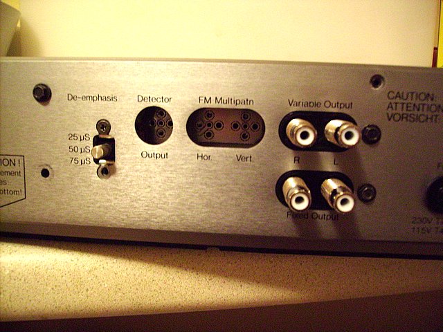
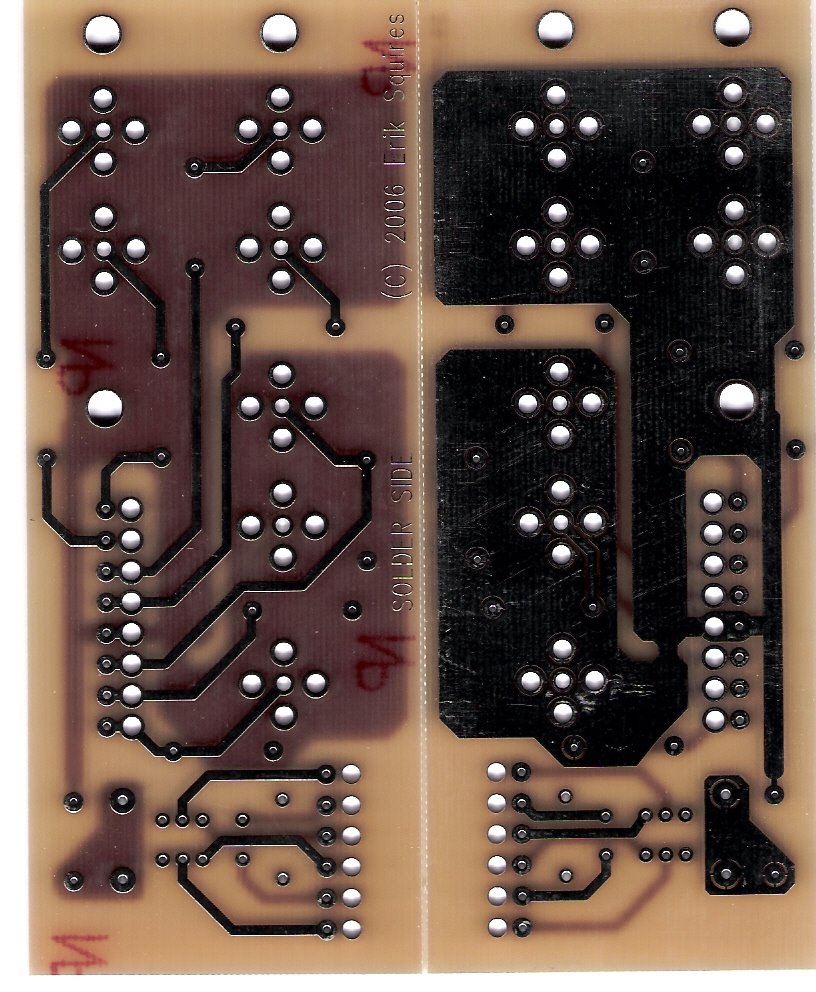
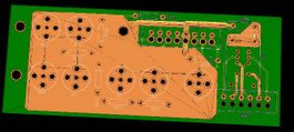
The Output Board
I received the Cardas output jacks Friday which means I was able to finish laying out the board with accurate device footprints. I will probably order a prototype run of the board this Wednesday, when you may see me selling the extras on E-bay if they fit.

I've also ordered all of the parts for it as well, which is just Vishay Mil-Spec Metal Film ultra low noise resistors. Everything else I will be pulling off the original board.
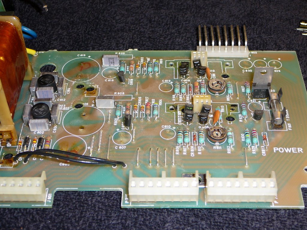
The Power Supply
When I bought the Tandberg 3001 tuner, I was informed something smoked, and when I took the cover off and found that in the power supply at least one cap had expanded beyond it's normal physical dimensions as well as a carbonized trimmer pot. In addition, I read in a Yahoo FM Tuner group that the power resistors were standard cement types, and sure enough mine were too.

As most of you know, electrolytic caps do have a limited shelf life, and are often the first to go in electronics gear, often taking out other components around them. So for the PS, I ordered abox full of Panasonic FM and FC capacitors, Kiwame Carbon Film and Vishay Metal Oxide resistors, new trimmer pots, and bags full of Panasonic Metal Film caps to use for bypassing. There will probably be a need for new transistors as well, but taking each one out and testing it would not be easy. Instead I will replace all the caps first, and then see if I can diagnose any bad transistors. After this, I will replace the trimmer pots, and power resistors.

Ok, before anyone starts, there is just no space in this thing for the fancy Solen/Auralcap/Multicap bypass caps that are all the rage so don't even start with me. If you aren't going to get hot without those, scroll down and droll at the CJ Power supply mods, then come back to this project. :) Maybe when I start making power supply boards for the 3001 from scratch we can discuss these. :) Just kidding, there's no way I have time for this with work and school. However, if you are a well-heeled devotee of the 3001 and really want a custom built power supply board with some seriously upgraded capabilities and components, send me a note. :) Maybe I can make a bunch of them at once.

Ok, so why not some Black Gate caps? Mostly, they have too long of a burn in time which starts over when you turn the unit off. According to what I read, it takes days for their electrolyte to become fully saturated and for you to get the full BG experience. With a vintage piece of gear like this with notorious overheating problems I just felt that BG's would not be worth the cost of ownership. I'm not going to leave it turned on for more than a day or weekend at a time. Besides, the Panasonic FM's are really really good compared to what was in there originally when this tuner was dominating the FM tuner ratings. Lastly, frankly, I need to see if this tuner ever turns on again. The power supply smoking may have ruined it, in which case spending a couple of hundred bucks on PS caps would be a complete waste.


On Progress and Humility
FYI, this tuner is going to rock when I am done, but honestly, if I had to design this tuner from scratch, there is NO way I could come close to the achievements Mr. Tandberg made to Audio, so I want to take a moment and express my gratitude at being able to in a small way connect with the work he and his engineers did in the 80s.

However, it is also true that many things have changed since then, so it is likely that Mr. Tandberg himself would have made improvements in several areas if he were still around. To begin with, double sided circuit boards are much cheaper in both production and prototype quantities. This is one major reason why I will make the amount of imrpovement in the output board that I will. It's worth going over because much that applies to it can apply to many re-builds of vintage equipment. The original board was single sided, forcing the ground plane had to share space with the audio traces. Because my version is double sided I can put down a massive ground plane on one side, with the signal traces on the other, which gives me better spacing which should lead to lower crosstalk and lower noise than the originals. The other reason this version will be better are the connectors. Rhodium over silver over brass will beat tin over plastic almost every time. As I noted above, I'm using very low noise Vishay resistors on the board as well. Lastly, I'm adding a surprise to the board specifically for that rare breed, the FM and cable junkie. He's not an average audiophile, nor is he an average cable head either. This species of audiophile still tries to find an FM station worth listening to AND he's a cable junkie. A very rare combination, usually found around Boston or LA or Chicago. But I won't say more until the boards are back. :)

The next place where things have gotten better than the Tandberg (and frankly, MY) days is in the size and quality of components. Electrolytic capacitors as well as power resistors have made major improvements in their quality as well as their size. A half watt or 5 watt resistor is much smaller than it used to be. Also, you can find some very high power resistors in metal film versions, which can take 30 watts in the space of a TO-220 case. High power, high stability and low noise in small packages. Sadly I can't use them without redesigning the power supply board (hah!) so I'm going to have to "settle" for some Kiwame's and Metal Oxides. But still, they are SO much smaller than their originals it's almost hard to use them. Two watt 1.2 Ohm Metal Oxide resistors are so small these days it may be difficult to put them in the place where the 2 1/2" long resistor went originally.

Also, we now have the ability to get very low inductance electrolytic capacitors in smaller packages than what Mr. Tandberg used as "standard." I'm talking about the Panasonic FM series here. They are smaller, have something like half the impedance of most other low inductance electrolytics when compared to Nichicon low impedance types. The one bit of a drag is that I can only find them with values up to 50V, so you have to step down to Panasonic FC types to get 63V caps. Not a big deal if you can apply some under-the-board metalized polyester film caps to make up for this small shortcoming.

My point to all of this is that I think if Mr. Tandberg had been succesful, and was still around, I think he would be designing with:

  • Double sided boards
  • Smaller, higher quaility components which....
  • Would let him get enough space for things like metal film resistors with heat sinks, bypass caps, larger ground planes and traces, along with holes in the board for the transistor and resistor heat sinks.
One of the things I've noticed about the 3001 is that I don't think I have ever owned a component so full of parts. I think this tuner has more parts than all of my other audio components put together. Putting together this many parts, on so many circuit boards using single sided technology in a low profile design really was an amazing bit of work. If I were to do the industrial design for gear like this I would have used a card cage design, and have made it twice as tall. This is closer to what Revox did during the same era, making their products easy to service but looking a bit like ham radios or toasters by comparison.

When I post again I'll put pictures of the insides of the Tandberg 3001 so you can see what I'm talking about when I say "full of parts."